I’m building a portable radio scanner to listen in on communications by police forces, both trunked and untrunked, but unencrypted. My primary motivation for building my own is to develop a formula for hacktivists who could scrounge up spare hardware to create a police scanner at a fraction of the cost of a commercially-available scanner such as the SDS100.
There are a variety of reasons why being able to eavesdrop on police communications could be useful. For example, hacktivists supporting a cell could operate an early warning system; being able to listen in on communications aids in threat intelligence which in turn informs decisions.
This blog post is structured such that it not only tells the story of how I created this scanner, but a reader can also follow along and build their own. If you have any questions or want advice on the build, feel free to contact me using my email on my “About” page.
Legal Disclaimer
I do not endorse illegal activity. Check your local laws and legislations. I’m not a lawyer and I’m not your lawyer, and this isn’t legal advice.
Overview
Since this project is essentially a radio-focused cyberdeck, I’ve taken to calling it the “RadioDeck.” Oozing with creativity there, I know.
The RadioDeck consists of a Raspberry Pi, a touchscreen display, a few rotary encoders, an SDR, and a power bank. It’s that simple. The rotary encoders allow operation without needing a keyboard or mouse. The entire build is housed inside of a portable carrying case.
Once assembled, it can be loaded with any SDR software such as Gqrx or sdrtrunk. I’m currently working on writing some of my own SDR software specifically created for the RadioDeck, which I’ll be discussing in Part 2.
Parts
For my specific build, I’ve used the following parts:
I also used the following miscellaneous parts which I can’t find links to, but I’m sure you could find at your local hardware and electronic stores:
- Female to Female Dupont Jumper Wires (2.54mm pitch)
- This is for connecting the rotary encoders to the Raspberry Pi.
- I recommend breaking 10 apart from a ribbon so the cabling stays tidy.
- HDMI to Micro HDMI Cable
- This is for connecting the display to the Raspberry Pi.
- I didn’t have the exact cable lying around, so I used an adapter.
- 2x USB C to USB A Cable
- This is for connecting the Raspberry Pi to the power bank. A USB C to USB C cable could also work for the power bank I used. Make sure it can supply sufficient power!
- Another one is also used for connecting the display to the Raspberry Pi for the purposes of power.
- 3.5mm Headphone Cable
- This helps provide easy access to connect headphones to the headphone jack.
- USB A “Extension” Cable
- This connects the RTL-SDR to the Raspberry Pi.
- SMA Male to Female Coax Cable
- This connects the RTL-SDR to the antenna.
- M2.5 Nuts, Bolts, Standoffs, and Threaded Inserts
- Some cable organization hooks and velcro.
- This is for securing the portable charger and SDR in place, and also for cable management.
I recommend using thin and flexible cables wherever possible, with the exception of the coax cable for signal integrity. Using thin and flexible cables, as long as it’s able to fulfill requirements like power delivery, will help fit everything into place.
I additionally fabricated two parts and 3D printed them for the build: the base, and the plate. The base helps position everything and provides positioning for standoffs, and the plate is the top cover that helps hide all the wiring. These parts were specifically fabricated for my project case:
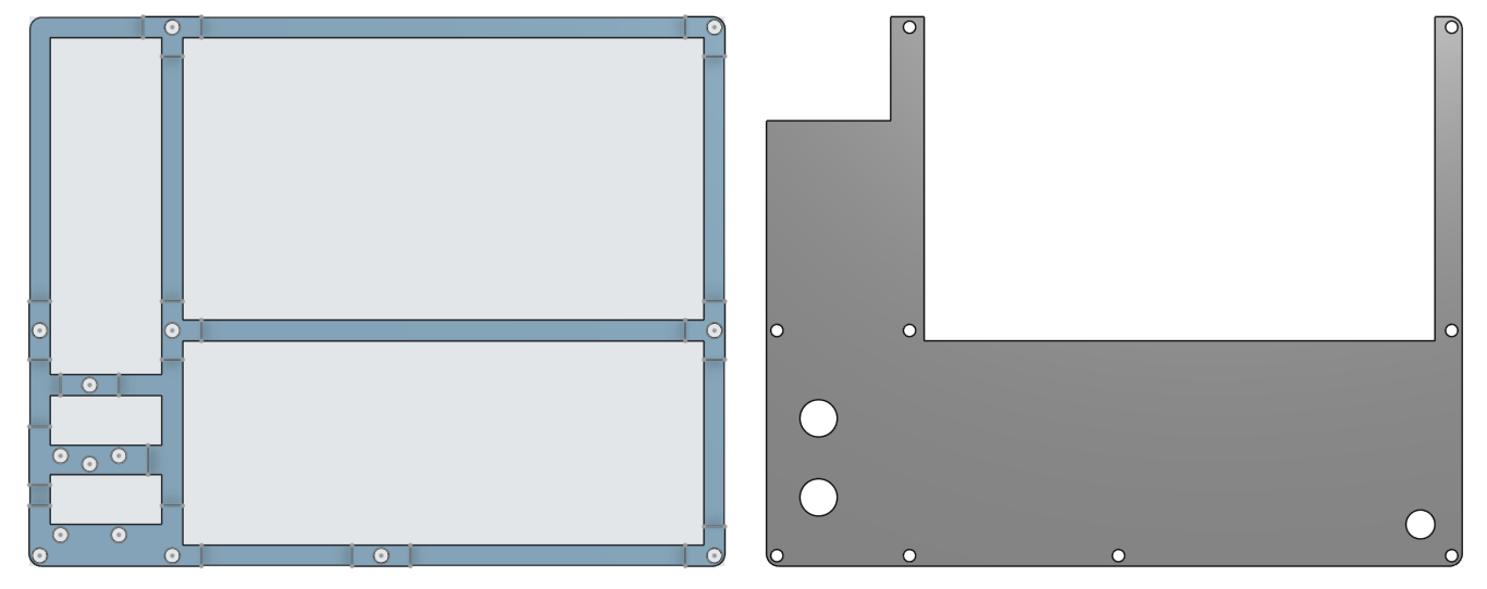
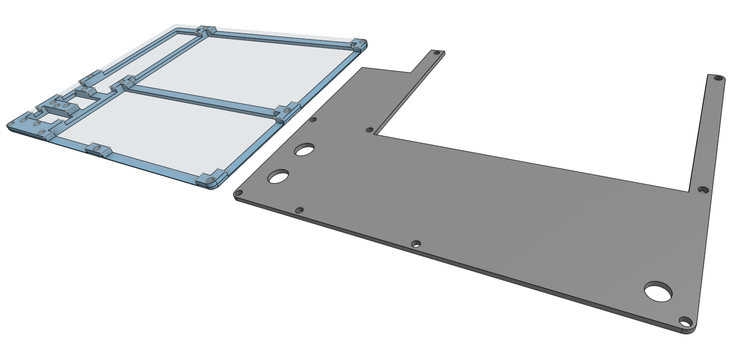
If you’re using the same specific parts as me, or want something to base your own off of, you can download them as STLs here:
If you want them in a different format, contact me and I’ll see what I can do.
Assembly
The base has some pilot holes for the threaded inserts to be melted into with a soldering iron.
Afterwards, you can attach the standoffs. I didn’t have any standoffs specifically the height of a standoff + 1.6mm (the thickness of the display’s PCB), so I added some 1.6mm nuts for structural standoffs around the display so that they’d all be the same height.
For the rotary encoders, I put some shorter standoffs underneath them – just enough for them to peek through the plate later on with the knob attached.
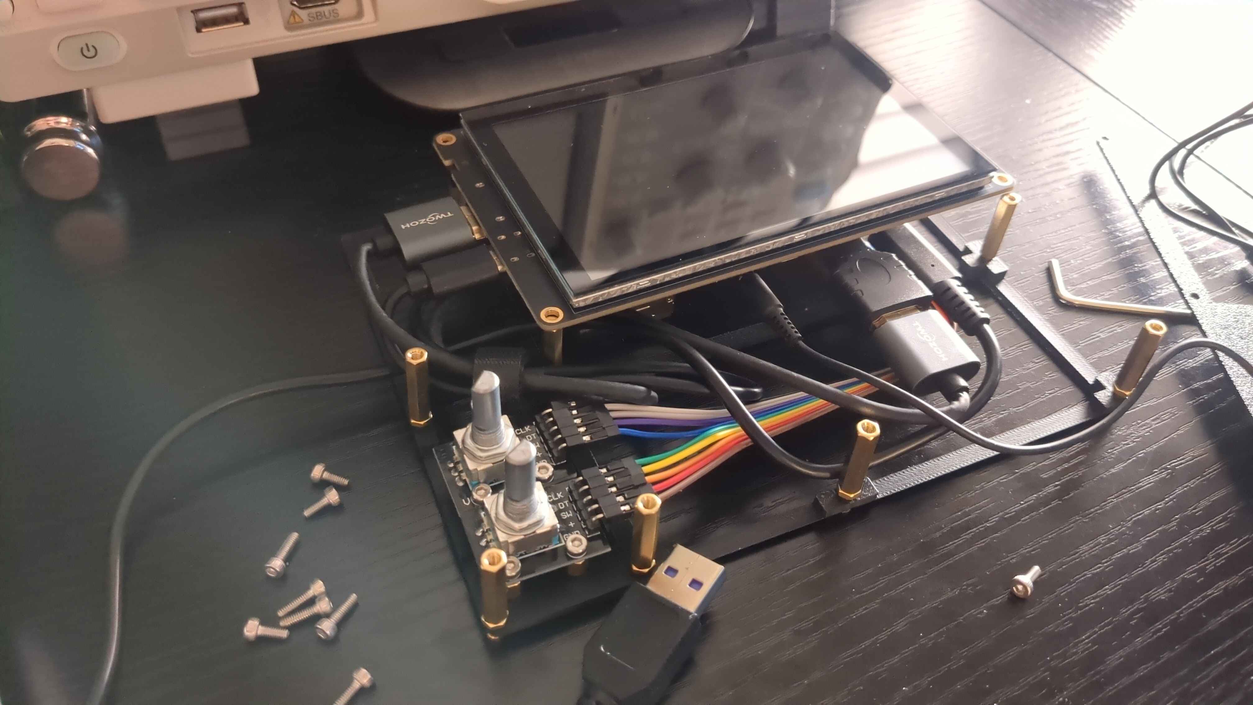
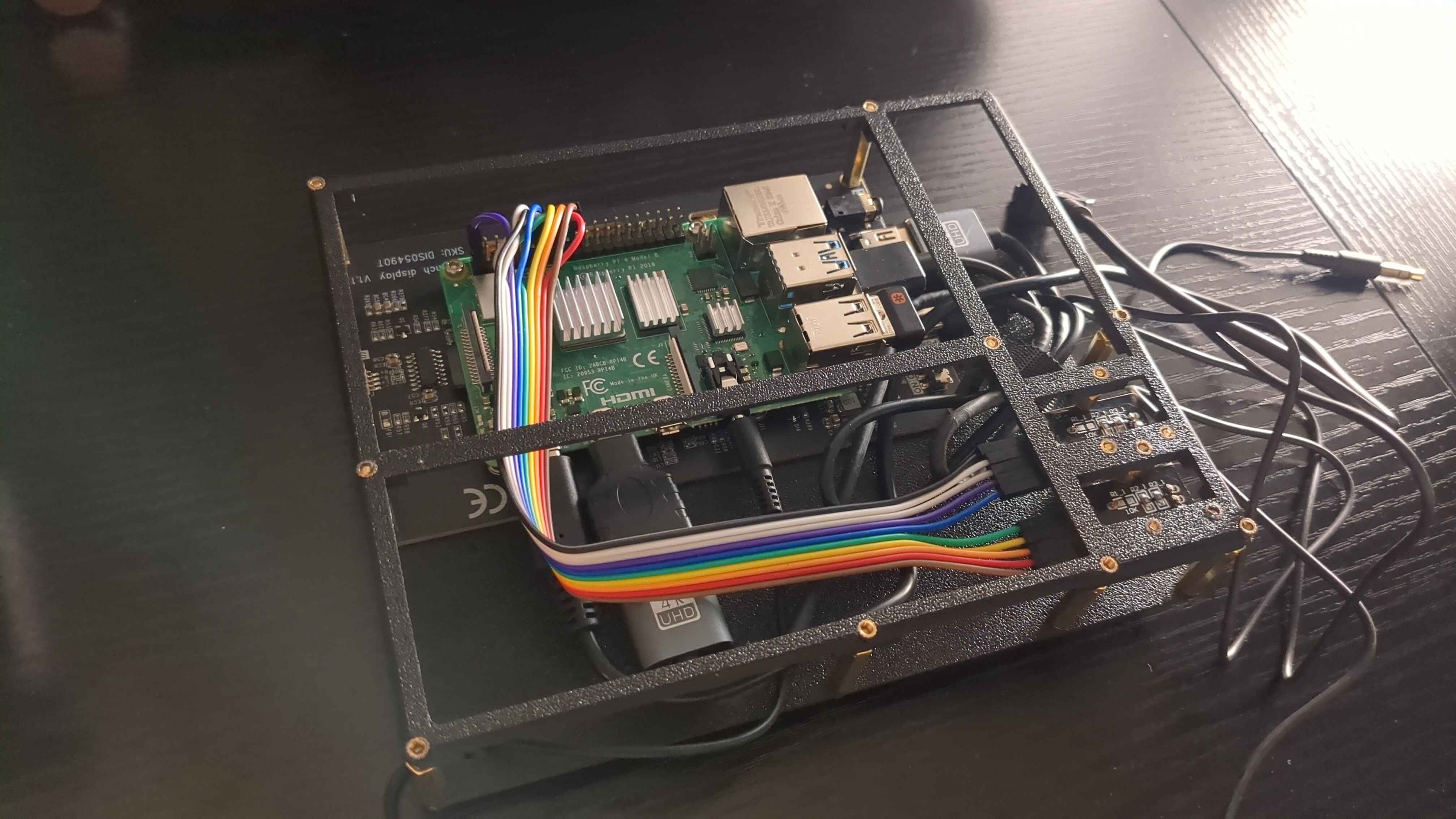
The wiring is pretty self-explanatory:
- Connect the display to the Pi. This means connecting both HDMI and power.
- The display I chose for this project conveniently allows the Pi to be mounted on the back of the display. This was very useful.
- Connect the rotary encoders to the Pi and mount them to their standoffs.
- I specifically used GPIO 17, 18, and 27, for KY-040 1’s CLK, DT, and SW and GPIO 22, 23, and 24 for KY-040 2’s CLK, DT, and SW, respectively. Of course, remember to connect their power and grounds to 3V3 and GND.
- Connect the power cable.
- Connect the USB extension cable.
- Connect the headphone cable.
- Use velcro to tidy up cables, wherever applicable.
Don’t worry if your cable management is a mess; that’s what the plate is for. You can attach the plate with M2.5 bolts. There’s a hole on the bottom right for you to pull the 3.5mm headphone cable through.
Here’s what it looks like underneath. I initially expected to need some kind of adhesive to attach the base to the bottom of the case, but it fit so perfectly and snugly that it doesn’t budge once inserted thanks to friction alone.
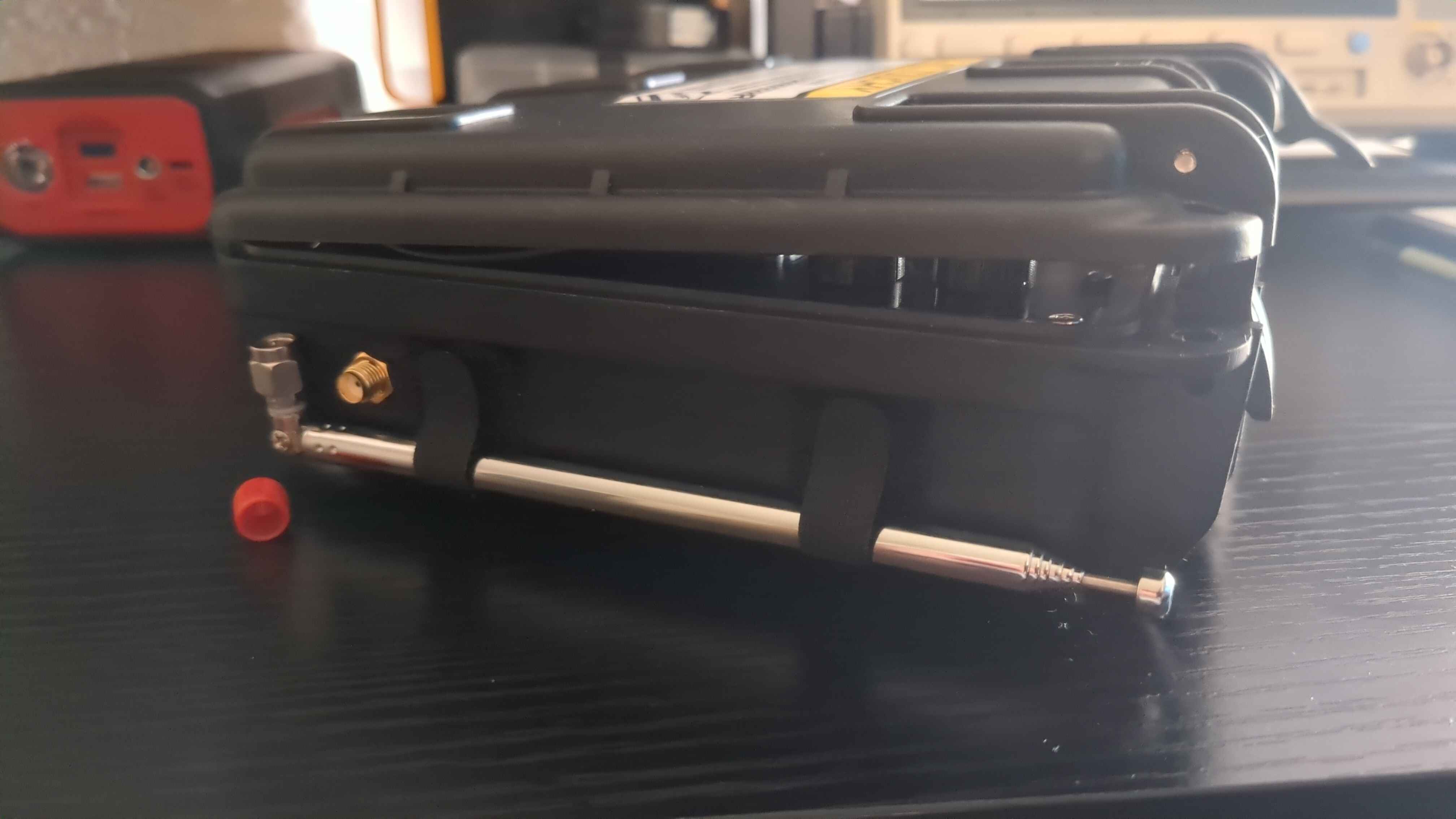
On the left side of the case, I drilled a hole for the SMA coax cable to mount to. I attached some velcro to use as an antenna holder.
After you drill the hole and mount the SMA coax cable into the slot, you can just drop your in-progress build directly into the case. If you have difficulty with this, you can attach the top plate separately after the rest of the parts are inside.
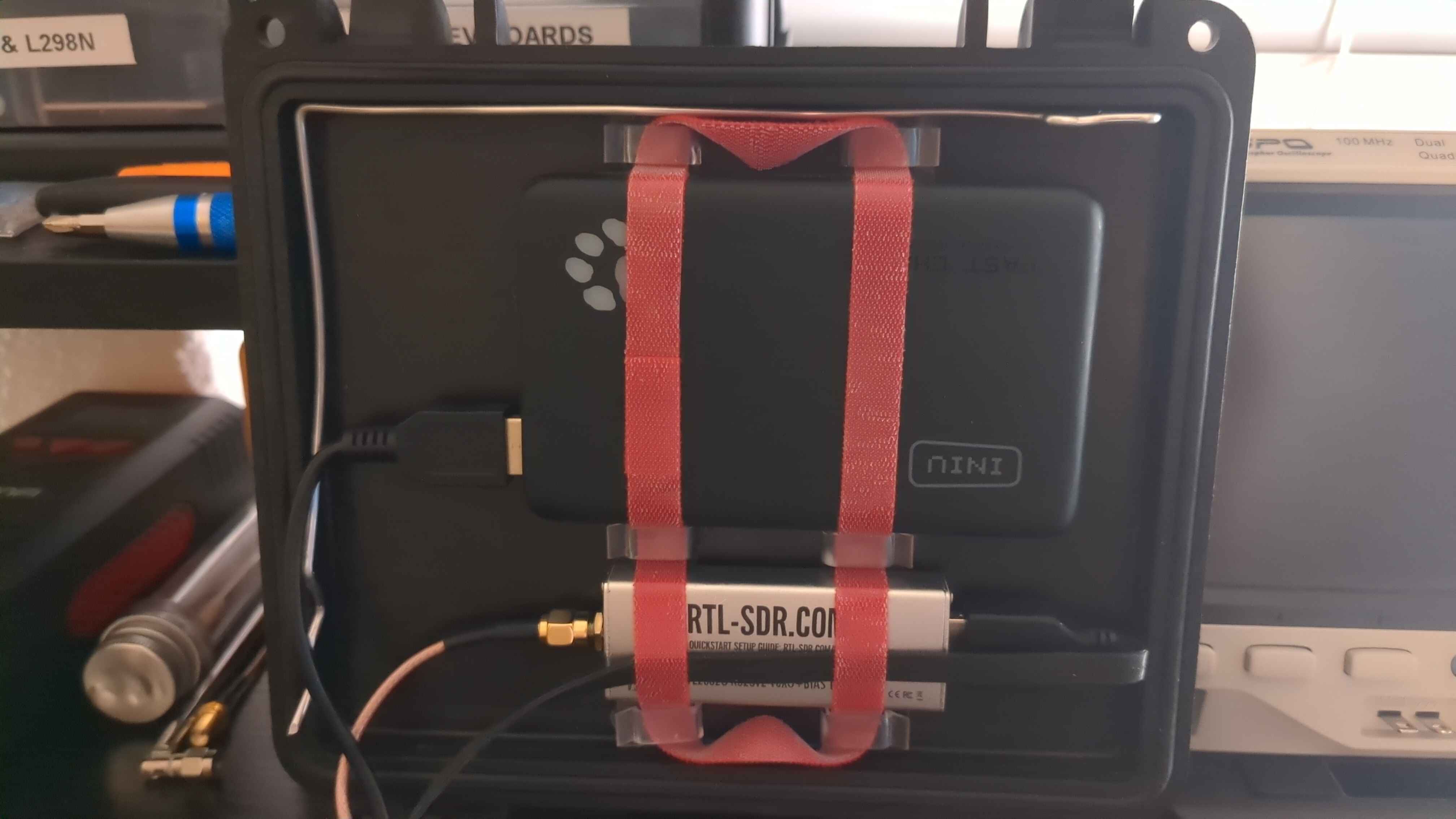
I used some cable hooks and velcro to secure the power bank and RTL-SDR into place. My SMA coax cable was the perfect length to just fit directly into the RTL-SDR from the antenna mounting slot on the side. This is also the stage where I connected the power bank and RTL-SDR to the Raspberry Pi.
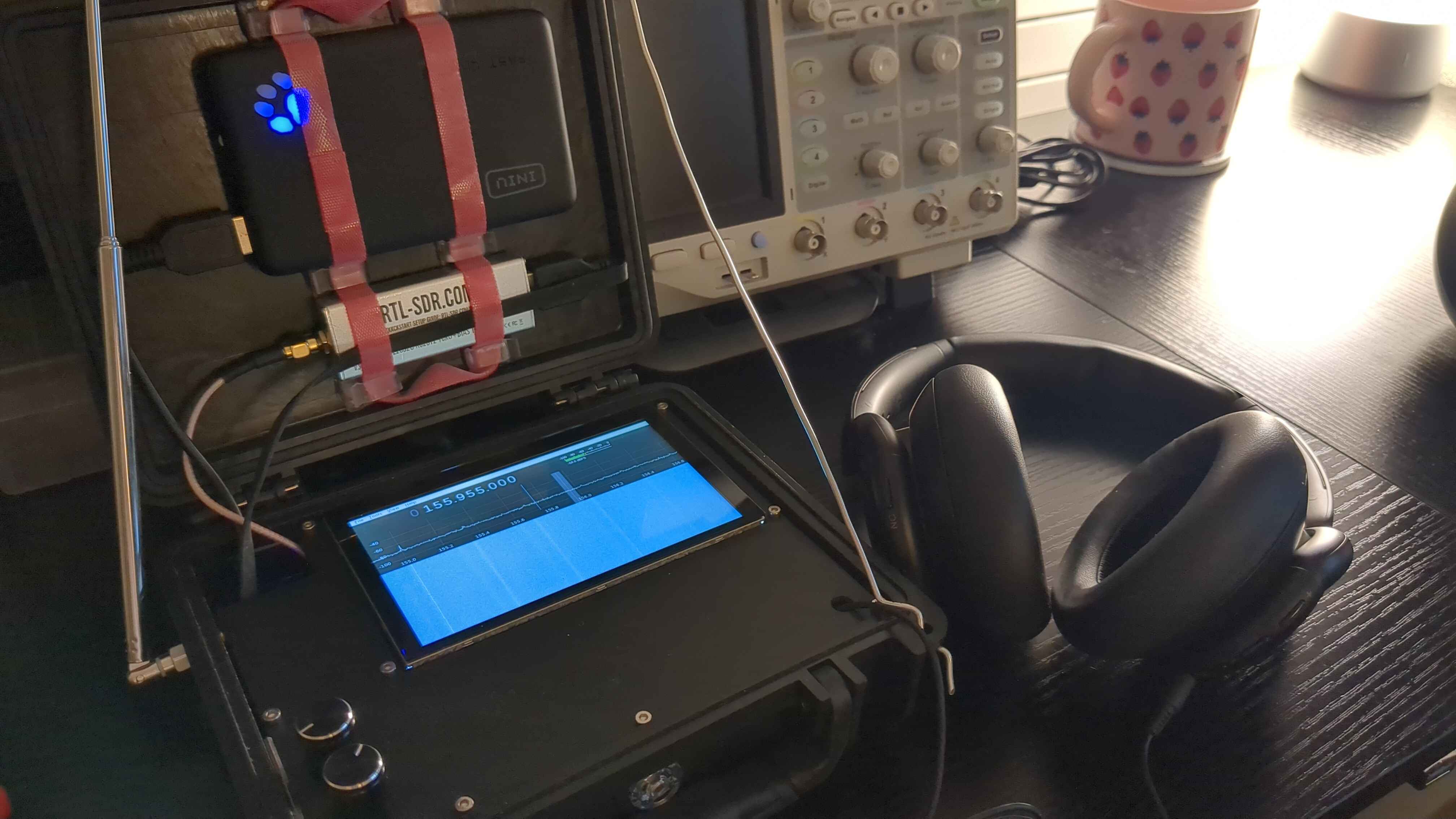
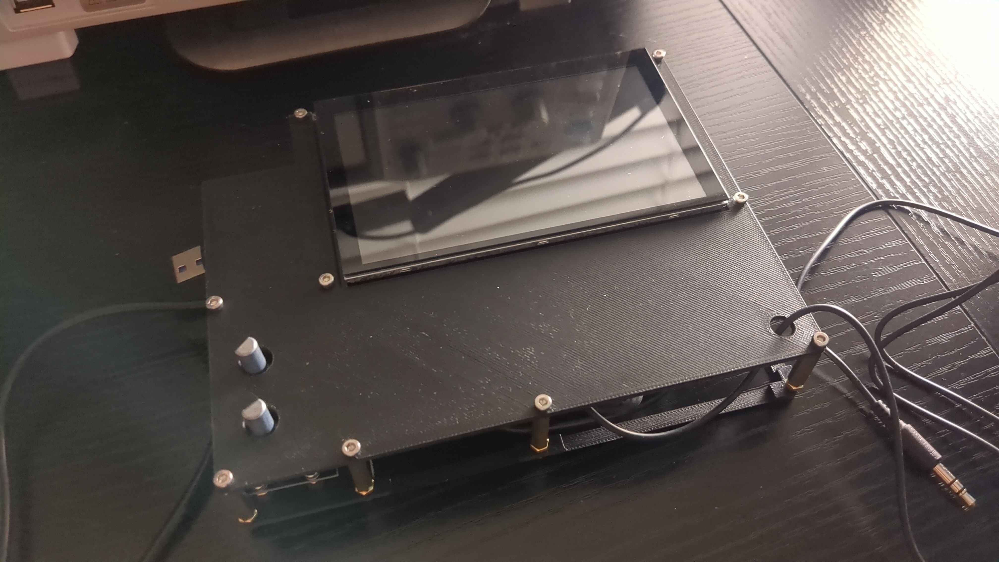
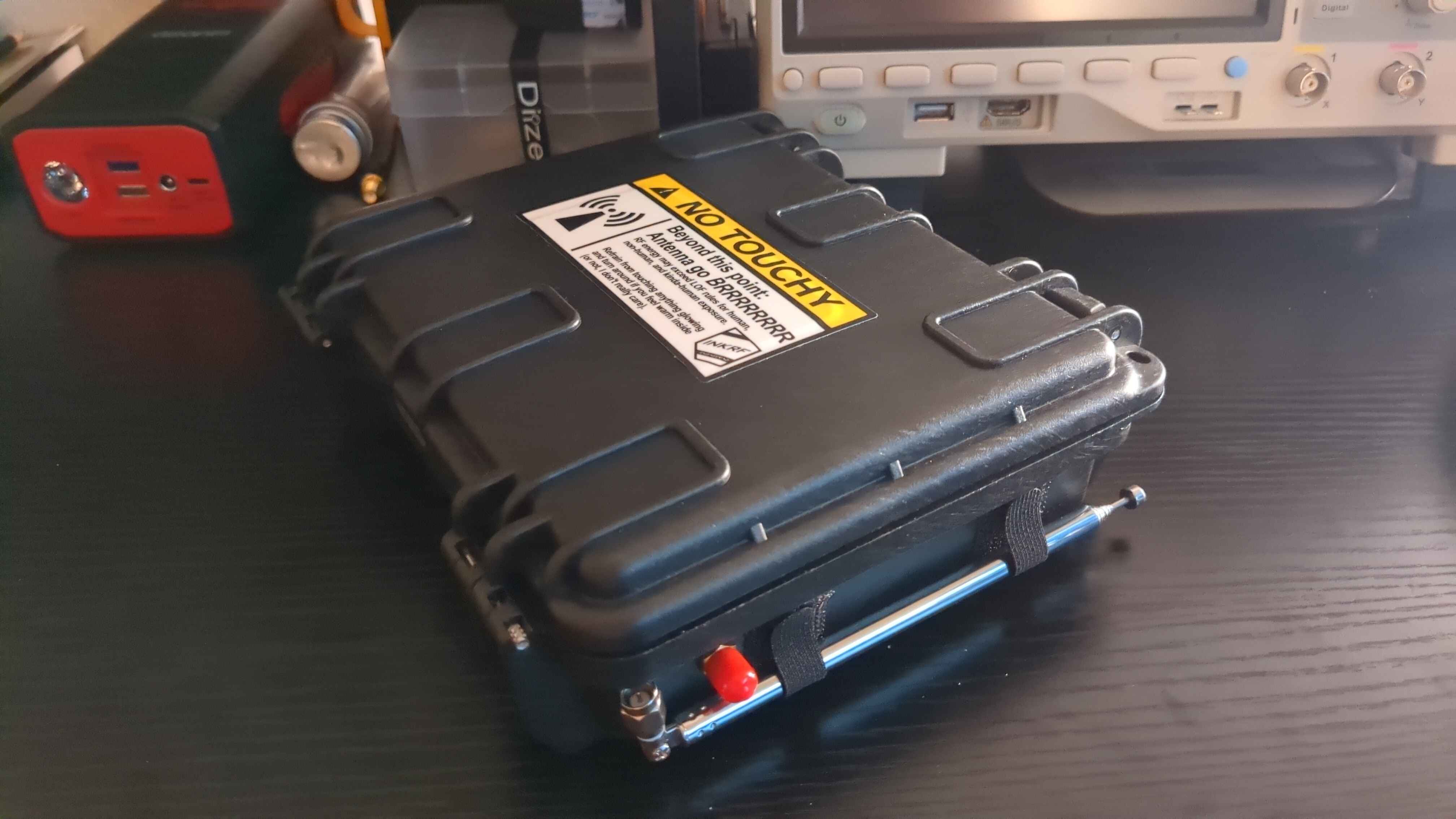
After attaching some knobs to the rotary encoders, the build is complete. Here’s what it looks like:

I additionally snuck a little Allen wrench on the bottom left corner of the case in the event that I ever needed to do maintenance on it – for convenience. I also fashioned a little prop bar out of some wire so that I don’t need to always be leaning the RadioDeck on something while it’s open.
I also slapped a sticker on it that a fellow radio hacker gave me while I was at DEF CON after spotting me wardriving. Thanks for the sticker, InkRF!
Part 2
That’s the entire hardware build! In Part 2, I’ll be talking about the software I’m writing for the RadioDeck. TBD.
Happy hacking!